Ultrasonic Testing (UT)

 Ultrasonic Testing

Picture 1

Ultrasonic Testing uses the same principle as is used in naval SONAR and fish finders. Ultra-high frequency sound is introduced into the part being inspected and if the sound hits a material with a different acoustic impedance (density and acoustic velocity), some of the sound will reflect back to the sending unit and can be presented on a visual display. By knowing the speed of the sound through the part (the acoustic velocity) and the time required for the sound to return to the sending unit, the distance to the reflector (the indication with the different acoustic impedance) can be determined. The most common sound frequencies used in UT are between 1.0 and 10.0 MHz, which are too high to be heard and do not travel through air. The lower frequencies have greater penetrating power but less sensitivity (the ability to "see" small indications), while the higher frequencies don't penetrate as deeply but can detect smaller indications.

The two most commonly used types of sound waves used in industrial inspections are the compression (longitudinal) wave and the shear (transverse) wave, as shown in picture 1. Compression waves cause the atoms in a part to vibrate back and forth parallel to the sound direction and shear waves cause the atoms to vibrate perpendicularly (from side to side) to the direction of the sound. Shear waves travel at approximately half the speed of longitudinal waves.

Sound is introduced into the part using an ultrasonic transducer ("probe") that converts electrical impulses from the UT machine into sound waves, then converts returning sound back into electric impulses that can be displayed as a visual representation on a digital or LCD screen (on older machines, a CRT screen). If the machine is properly calibrated, the operator can determine the distance from the transducer to the reflector, and in many cases, an experienced operator can determine the type of discontinuity (like slag, porosity or cracks in a weld) that caused the reflector. Because ultrasound will not travel through air (the atoms in air molecules are too far apart to transmit ultrasound), a liquid or gel called "couplant" is used between the face of the transducer and the surface of the part to allow the sound to be transmitted into the part.


UT Techniques


Straight Beam
Picture 2

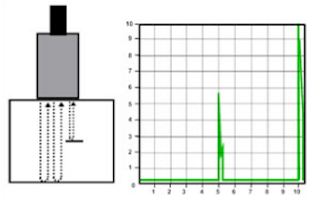
Straight beam inspection uses longitudinal waves to interrogate the test piece as shown at the right. If the sound hits an internal reflector, the sound from that reflector will reflect to the transducer faster than the sound coming back from the back-wall of the part due to the shorter distance from the transducer. This results in a screen display like that shown at the right in Picture 2. Digital thickness testers use the same process, but the output is shown as a digital numeric readout rather than a screen presentation.

Angle Beam


Picture 3


Angle beam inspection uses the same type of transducer but it is mounted on an angled wedge (also called a "probe") that is designed to transmit the sound beam into the part at a known angle. The most commonly used inspection angles are 45o, 60o and 70o, with the angle being calculated up from a line drawn through the thickness of the part (not the part surface). A 60o probe is shown in Picture 3. If the frequency and wedge angle is not specified by the governing code or specification, it is up to the operator to select a combination that will adequately inspect the part being tested.

In angle beam inspections, the transducer and wedge combination (also referred to as a "probe") is moved back and forth towards the weld so that the sound beam passes through the full volume of the weld. As with straight beam inspections, reflectors aligned more or less perpendicular to the sound beam will send sound back to the transducer and are displayed on the screen.

Immersion Testing


Picture 4


Immersion Testing is a technique where the part is immersed in a tank of water with the water being used as the coupling medium to allow the sound beam to travel between the transducer and the part. The UT machine is mounted on a movable platform (a "bridge") on the side of the tank so it can travel down the length of the tank. The transducer is swivel-mounted on at the bottom of a waterproof tube that can be raised, lowered and moved across the tank. The bridge and tube movement permits the transducer to be moved on the X-, Y- and Z-axes. All directions of travel are gear driven so the transducer can be moved in accurate increments in all directions, and the swivel allows the transducer to be oriented so the sound beam enters the part at the required angle. Round test parts are often mounted on powered rollers so that the part can be rotated as the transducer travels down its length, allowing the full circumference to be tested. Multiple transducers can be used at the same time so that multiple scans can be performed.
Through Transmission
Through transmission inspections are performed using two transducers, one on each side of the part as shown in Picture 4. The transmitting transducer sends sound through the part and the receiving transducer receives the sound. Reflectors in the part will cause a reduction in the amount of sound reaching the receiver so that the screen presentation will show a signal with a lower amplitude (screen height).

Phased Array

Phased array inspections are done using a probe with multiple elements that can be individually activated. By varying the time when each element is activated, the resulting sound beam can be "steered", and the resulting data can be combined to form a visual image representing a slice through the part being inspected.

Time of Flight Diffraction

Time of Flight Diffraction (TOFD) uses two transducers located on opposite sides of a weld with the transducers set at a specified distance from each other. One transducer transmits sound waves and the other transducer acting as a receiver. Unlike other angle beam inspections, the transducers are not manipulated back and forth towards the weld, but travel along the length of the weld with the transducers remaining at the same distance from the weld. Two sound waves are generated, one travelling along the part surface between the transducers, and the other travelling down through the weld at an angle then back up to the receiver. When a crack is encountered, some of the sound is diffracted from the tips of the crack, generating a low strength sound wave that can be picked up by the receiving unit. By amplifying and running these signals through a computer, defect size and location can be determined with much greater accuracy than by conventional UT methods.
READMORE
 

Radiographic Testing (RT)

RADIOGRAPHY TEST

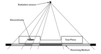
Industrial radiography involves exposing a test object to penetrating radiation so that the radiation passes through the object being inspected and a recording medium placed against the opposite side of that object. For thinner or less dense materials such as aluminum, electrically generated x-radiation (X-rays) are commonly used, and for thicker or denser materials, gamma radiation is generally used.

Gamma radiation is given off by decaying radioactive materials, with the two most commonly used sources of gamma radiation being Iridium-192 (Ir-192) and Cobalt-60 (Co-60). IR-192 is generally used for steel up to 2-1/2 - 3 inches, depending on the Curie strength of the source, and Co-60 is usually used for thicker materials due to its greater penetrating ability.

The recording media can be industrial x-ray film or one of several types of digital radiation detectors. With both, the radiation passing through the test object exposes the media, causing an end effect of having darker areas where more radiation has passed through the part and lighter areas where less radiation has penetrated. If there is a void or defect in the part, more radiation passes through, causing a darker image on the film or detector, as shown in Figure 8.

RT Techniques

Film Radiography


Film radiography uses a film made up of a thin transparent plastic coated with a fine layer of silver bromide on one or both sides of the plastic. When exposed to radiation these crystals undergo a reaction that allows them, when developed, to convert to black metallic silver. That silver is then "fixed" to the plastic during the developing process, and when dried, becomes a finished radiographic film.

To be a usable film, the area of interest (weld area, etc.) on the film must be within a certain density (darkness) range and must show enough contrast and sensitivity so that discontinuities of interest can be seen. These items are a function of the strength of the radiation, the distance of the source from the film and the thickness of the part being inspected. If any of these parameters are not met, another exposure ("shot") must be made for that area of the part.

Computed Radiography


Computed radiography (CR) is a transitional technology between film and direct digital radiography. This technique uses a reusable, flexible, photo-stimulated phosphor (PSP) plate which is loaded into a cassette and is exposed in a manner similar to traditional film radiography. The cassette is then placed in a laser reader where it is scanned and translated into a digital image, which take from one to five minutes. The image can then be uploaded to a computer or other electronic media for interpretation and storage.

Computed Tomography

Computed tomography (CT) uses a computer to reconstruct an image of a cross sectional plane of an object as opposed to a conventional radiograph, as shown in Figure 9. The CT image is developed from multiple views taken at different viewing angles that are reconstructed using a computer. With traditional radiography, the position of internal discontinuities cannot be accurately determined without making exposures from several angles to locate the item by triangulation. With computed tomography, the computer triangulates using every point in the plane as viewed from many different directions.


Digital Radiography

Digital radiography (DR) digitizes the radiation that passes through an object directly into an image that can be displayed on a computer monitor. The three principle technologies used in direct digital imaging are amorphous silicon, charge coupled devices (CCDs), and complementary metal oxide semiconductors (CMOSs). These images are available for viewing and analysis in seconds compared to the time needed to scan in computed radiography images. The increased processing speed is a result of the unique construction of the pixels; an arrangement that also allows a superior resolution than is found in computed radiography and most film applications.
READMORE
 

Liquid Penetrant Testing (PT)

Liquid Penetrant Testing (PT)

Pic1 : Using Penetrant Test


The basic principle of liquid penetrant testing is that when a very low viscosity (highly fluid) liquid (the penetrant) is applied to the surface of a part, it will penetrate into fissures and voids open to the surface. Once the excess penetrant is removed, the penetrant trapped in those voids will flow back out, creating an indication. Penetrant testing can be performed on magnetic and non-magnetic materials, but does not work well on porous materials. Penetrants may be "visible", meaning they can be seen in ambient light, or fluorescent, requiring the use of a "black" light. The visible dye penetrant process is shown in Pic 1. When performing a PT inspection, it is imperative that the surface being tested is clean and free of any foreign materials or liquids that might block the penetrant from entering voids or fissures open to the surface of the part. After applying the penetrant, it is permitted to sit on the surface for a specified period of time (the "penetrant dwell time"), then the part is carefully cleaned to remove excess penetrant from the surface. When removing the penetrant, the operator must be careful not to remove any penetrant that has flowed into voids. A light coating of developer is then be applied to the surface and given time ("developer dwell time") to allow the penetrant from any voids or fissures to seep up into the developer, creating a visible indication. Following the prescribed developer dwell time, the part is inspected visually, with the aid of a black light for fluorescent penetrants. Most developers are fine-grained, white talcum-like powders that provide a color contrast to the penetrant being used.


Steps to use of penetrant

1.Clean the surface of the material

Pic 2 : Use Cleaner/ Removal

Cleaned the surface of test beforehand to dirt , paint , oil , or plump did not result in an indication that are not very relevant or false .A method of cleansing can use a cleaning fluid ( cleaner / remover ) , for cleansing redusi an alkali , or steam degreasing .The ultimate goal of this step is a surface that is cleanly in which each defect visible and formed to the surface , dry , and free from contamination.

2. Spray penetrant into the area to be inspection:


Pic 3 : Use Penetrant Liquid

Test penetrant were then applied to the surface of the material material tested. Penetrant should be given ' Dwelling Time ' to percolate into each possibilities defect that is usually 5 to 30 minutes. Dwelling Time especially depends on penetrant used, material tested and size deficiency sought. As expected, small hitch takes more time old in penetrasinya. Because the incompatible they need to be careful to not to apply a solvent based penetrant to the surface that will be examined with penetrant that has been washed.


3. Clean up the Penetrant

Pic 4 : Clean up the Penetrant

After used Penetrant Liquid, please to Clean up the Penetrant on workpiece, the clean up can use Cloat Former, the cleaner/remover can to spray at cloat former, and than clean up the work piece with cloat former.


4. Use Developer Liquid


Pic 5 : Use Developer Liquid

After penetrant have been in clean in the surface of a workpiece use cleaner , and next use developers on a workpiece , wait 5-1 minutes . If there is an indication defect welds , so defect welds will appear in a workpiece

Developers interesting penetrant from defect come out to the surface to form a visible indication , is commonly known as blood - out .Any area blood - out can indicating the location of the , orientation and a kind of the possibility of a flaw on a surface. Interpret the results and characterization flaws in an indication that discoveries could be require various training and / or experience size an indication is not actual size from defect.


5. Inspection

Pic 6 : Inspection


Inspector will use visible light in intensity adequate ( 100 feet -- wax or 1100 lux typical ) to dye penetrant look.Ultraviolet ( uv-a ) of radiation intensity adequate ( 1,000 mikro-watt per centimeters public square, along with low level light ambient ( less than 2 foot-candle ) for examination penetrant fluorescent.Inspection the surface test to do after 10 to 30 minutes development, based on the type of products.

6. Post Cleaning


Pic 7 : Post Cleaning


If already convinced with the indications defect welds that appears , then immediately do cleaning on a workpiece .To maintain a workpiece the lifetime .
READMORE