The Charpy impact test

The Charpy impact test


The Charpy impact test, also known as the Charpy V-notch test, is a standardized high strain-rate test which determines the amount of energy absorbed by a material during fracture. This absorbed energy is a measure of a given material's notch toughness and acts as a tool to study temperature-dependent ductile-brittle transition. It is widely applied in industry, since it is easy to prepare and conduct and results can be obtained quickly and cheaply. A disadvantage is that some results are only comparative.

The test was developed around 1900 by S.B. Russell (1898, American) and Georges Charpy (1901, French). The test became known as the Charpy test in the early 1900s due to the technical contributions and standardization efforts by Charpy. The test was pivotal in understanding the fracture problems of ships during WWII.

Today it is utilized in many industries for testing materials, for example the construction of pressure vessels and bridges to determine how storms will affect the materials used.
In 1896 S. B. Russell introduced the idea of residual fracture energy and devised a pendulum fracture test. Russell's initial tests measured un-notched samples. In 1897 Frémont introduced a test trying to measure the same phenomenon using a spring-loaded machine. In 1901 Georges Charpy proposed a standardized method improving Russell's by introducing a redesigned pendulum, notched sample and generally giving precise specifications.

Definition

he apparatus consists of a pendulum of known mass and length that is dropped from a known height to impact a notched specimen of material. The energy transferred to the material can be inferred by comparing the difference in the height of the hammer before and after the fracture (energy absorbed by the fracture event).
The notch in the sample affects the results of the impact test,  thus it is necessary for the notch to be of regular dimensions and geometry. The size of the sample can also affect results, since the dimensions determine whether or not the material is in plane strain. This difference can greatly affect conclusions made.
The "Standard methods for Notched Bar Impact Testing of Metallic Materials" can be found in ASTM E23, ISO 148-1 or EN 10045-1, where all the aspects of the test and equipment used are described in detail.
The Charpy Impact Test is commonly used on metals, but is also applied to composites, ceramics and polymers. With the Charpy impact test one most commonly evaluates the relative toughness of a material, and as such, it is used as a quick and economical quality control device.

Charpy Sample


The standard Charpy Impact Test specimen consist of a bar of metal, or other material, 55x10x10mm having a notch machined across one of the larger dimensions.

V-notch: 2mm deep, with 45° angle and 0.25mm radius along the base
U-notch and keyhole notch: 5mm deep notch with 1mm radius at base of notch

Sample sizes

According to ASTM A370, the standard specimen size for Charpy impact testing is 10 mm × 10mm × 55mm. Subsize specimen sizes are: 10 mm × 7.5 mm × 55mm, 10 mm × 6.7 mm × 55 mm, 10 mm × 5 mm × 55 mm, 10 mm × 3.3 mm × 55 mm, 10 mm × 2.5 mm × 55 mm. Details of specimens as per ASTM A370 (Standard Test Method and Definitions for Mechanical Testing of Steel Products).

According to EN 10045-1, standard specimen sizes are 10 mm × 10 mm × 55 mm. Subsize specimens are: 10 mm × 7.5 mm × 55 mm and 10 mm × 5 mm × 55 mm.


According to ISO 148, standard specimen sizes are 10 mm × 10 mm × 55 mm. Subsize specimens are: 10 mm × 7.5 mm × 55 mm, 10 mm × 5 mm × 55 mm and 10 mm × 2.5 mm × 55mm.

Quantitative results
The quantitative result of the impact tests the energy needed to fracture a material and can be used to measure the toughness of the material. There is a connection to the yield strength but it cannot be expressed by a standard formula. Also, the strain rate may be studied and analyzed for its effect on fracture.

The ductile-brittle transition temperature (DBTT) may be derived from the temperature where the energy needed to fracture the material drastically changes. However, in practice there is no sharp transition and it is difficult to obtain a precise transition temperature (it is really a transition region). An exact DBTT may be empirically derived in many ways: a specific absorbed energy, change in aspect of fracture (such as 50% of the area is cleavage), etc.

Qualitative results

The qualitative results of the impact test can be used to determine the ductility of a material. If the material breaks on a flat plane, the fracture was brittle, and if the material breaks with jagged edges or shear lips, then the fracture was ductile. Usually a material does not break in just one way or the other, and thus comparing the jagged to flat surface areas of the fracture will give an estimate of the percentage of ductile and brittle fracture.

WHY IS IMPACT TESTING IMPORTANT?

Impact resistance is one of the most important properties for a part designer to consider, and without question, the most difficult to quantify. The impact resistance of a part is, in many applications, a critical measure of service life. More importantly these days, it involves the perplexing problem of product safety and liability.
One must determine:

1.The impact energies the part can be expected to see in its lifetime
2. The type of impact that will deliver that energy, and then
3. Select a material that will resist such assaults over the projected life span

Molded-in stresses, polymer orientation, weak spots (e.g. weld lines or gate areas), and part geometry will affect impact performance. Impact properties also change when additives, e.g. coloring agents, are added to plastics.


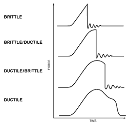
DUCTILE VS. BRITTLE

Most real world impacts are biaxial rather than unidirectional.

Further complication is offered by the choice of failure modes: ductile or brittle. Brittle materials take little energy to start a crack, little more to propagate it to a shattering climax. Other materials possess ductility to varying degrees. Highly ductile materials fail by puncture in drop weight testing and require a high energy load to initiate and propagate the crack.

Many materials are capable of either ductile or brittle failure, depending upon the type of test and rate and temperature conditions. They possess a ductile/brittle transition that actually shifts according to these variables.



Tensile testing


Tensile testing

Pic 1 : Tensile testing 


Tensile testing, is also known as tension testing, is a fundamental materials science test in which a sample is subjected to a controlled tension until failure. The results from the test are commonly used to select a material for an application, for quality control, and to predict how a material will react under other types of forces. Properties that are directly measured via a tensile test are ultimate tensile strength, maximum elongation and reduction in area From these measurements the following properties can also be determined:Young's modulus, Poisson's ratio, yield strength, and strain-hardening characteristics. Uniaxial tensile testing is the most commonly used for obtaining the mechanical characteristics of isotropic materials. For anisotropic materials, such as composite materials and textiles, biaxial tensile testing is required.

Tensile specimen

Pic 2 : Tensile specimen


Tensile specimens made from an aluminum alloy. The left two specimens have a round cross-section and threaded shoulders. The right two are flat specimens designed to be used with serrated grips.

A tensile specimen is a standardized sample cross-section. It has two shoulders and a gage (section) in between. The shoulders are large so they can be readily gripped, whereas the gauge section has a smaller cross-section so that the deformation and failure can occur in this area.


The shoulders of the test specimen can be manufactured in various ways to mate to various grips in the testing machine (see the image below). Each system has advantages and disadvantages; for example, shoulders designed for serrated grips are easy and cheap to manufacture, but the alignment of the specimen is dependent on the skill of the technician. On the other hand, a pinned grip assures good alignment. Threaded shoulders and grips also assure good alignment, but the technician must know to thread each shoulder into the grip at least one diameter's length, otherwise the threads can strip before the specimen fractures

In large castings and forgings it is common to add extra material, which is designed to be removed from the casting so that test specimens can be made from it. These specimens may not be exact representation of the whole workpiece because the grain structure may be different throughout. In smaller workpieces or when critical parts of the casting must be tested, a workpiece may be sacrificed to make the test specimens. For workpieces that are machined from bar stock, the test specimen can be made from the same piece as the bar stock.


Various shoulder styles for tensile specimens. Keys A through C are for round specimens, whereas keys D and E are for flat specimens. Key:

A. A Threaded shoulder for use with a threaded grip
B. A round shoulder for use with serrated grips
C. A butt end shoulder for use with a split collar
D. A flat shoulder for used with serrated grips
E. A flat shoulder with a through hole for a pinned grip


The repeatability of a testing machine can be found by using special test specimens meticulously made to be as similar as possible.
A standard specimen is prepared in a round or a square section along the gauge length, depending on the standard used. Both ends of the specimens should have sufficient length and a surface condition such that they are firmly gripped during testing. The initial gauge length Lo is standardized (in several countries) and varies with the diameter (Do) or the cross-sectional area (Ao) of the specimen as listed.


The following tables gives examples of test specimen dimensions and tolerances per standard ASTM E8.
Flat test specimen

Round test specimen.


A universal testing machine (Hegewald & Peschke)

The most common testing machine used in tensile testing is the universal testing machine. This type of machine has two crossheads; one is adjusted for the length of the specimen and the other is driven to apply tension to the test specimen. There are two types: hydraulicpowered and electromagnetically powered machines.
The machine must have the proper capabilities for the test specimen being tested. There are four main parameters: force capacity, speed,precision and accuracy. Force capacity refers to the fact that the machine must be able to generate enough force to fracture the specimen. The machine must be able to apply the force quickly or slowly enough to properly mimic the actual application. Finally, the machine must be able to accurately and precisely measure the gauge length and forces applied; for instance, a large machine that is designed to measure long elongations may not work with a brittle material that experiences short elongations prior to fracturing.

Alignment of the test specimen in the testing machine is critical, because if the specimen is misaligned, either at an angle or offset to one side, the machine will exert a bending force on the specimen. This is especially bad for brittle materials, because it will dramatically skew the results. This situation can be minimized by using spherical seats or U-joints between the grips and the test machine. If the initial portion of the stress–strain curve is curved and not linear, it indicates the specimen is misaligned in the testing machine.


The strain measurements are most commonly measured with an extensometer, but strain gauges are also frequently used on small test specimen or when Poisson's ratio is being measured. Newer test machines have digital time, force, and elongation measurement systems consisting of electronic sensors connected to a data collection device (often a computer) and software to manipulate and output the data. However, analog machines continue to meet and exceed ASTM, NIST, and ASM metal tensile testing accuracy requirements, continuing to be used today.


Performing a Tensile Test

Though a tensile test is relatively simple and has been around for a very long time, some thought and consideration must be done to ensure that the test will have valid results. Factors involved are the specimen shape and dimensions, the choice of grips and faces, and many more.

Specimen Shape

The specimen's shape is usually defined by the standard or specification being utilized, e.g., ASTM E8 or D638. Its shape is important because you want to avoid having a break or fracture within the area being gripped. So, standards have been developed to specify the shape of the specimen to ensure the break will occur in the "gage length" (2 inches are frequently used) by reducing the cross sectional area or diameter of the specimen throughout the gage length. This has the effect of increasing the stress in the gage length since stress is inversely proportional to the cross sectional area under load.

Grip and Face Selection

Face and grip selection is a very important factor. By not choosing the correct set up, your specimen may slip or even break inside the gripped area ("jaw break"). This would lead to invalid results. The faces should cover the entire tab or area to be gripped. You do not want to use serrated faces when testing materials that are very ductile. Sometimes covering the serrated faces with masking tape will soften the bite preventing damage to the specimen. 

Specimen Alignment

Vertical alignment of the specimen is an important factor to avoid side loading or bending moments created in the specimen. Mounting the specimen in the upper grip assembly first then allowing it to hang freely will help to maintain alignment for the test.


TYPICAL MATERIALS & STANDARDS

  • Ceramics - ISO 15733, ISO 15490, ISO 17561
  • Composites - MIL-HDBK-17, ISO 527 (Parts 4 & 5 on FRP composites)
  • Elastomers & Rubber - ASTM D412, ISO 37
  • Metals - ASTM E8 (at room temperature, E21 (high temperature, BS EN 10002, ISO 6892 (at ambient temperature), ISO 783 (elevated temperature), ISO 15579 (at low temperature)
  • Paper - ASTM D828, ISO 1924 (Parts 1 & 2), ISO 3781
  • Plastics - ISO 527, ASTM D638
  • Textiles & Yarns - ASTM D76, D3822, D2256, D2653, ISO 9073 (Part 3 on nonwovens), ISO 13934, ISO 13935
  • Wood - ISO 9086, 3345, 3346


Destructive Testing

destructive testing are defined as those tests that are made to a material through the use of tools or machines, which produce an irreversible alteration of their chemical composition or dimensional geometry.
destructive testing are performed on adhesive or adhesive joints that have 4 main objectives:
·         Get the features and mechanical properties of the adhesive.
·         Made comparative between different adhesives.
·         Check the conditions of application as well as adhesives and preparation of substrates or adherents.
·         Simulate the ageing conditions of the adhesive bonding during his lifetime, in order to predict their behavior.
Due that the adhesive process is consider a special process, it is advisable or necessary, depending on the requirements of the bonded joint, a series of specimens at the same time it makes application of the adhesive, in order to check the environmental conditions, surface preparation and product set of the adhesive system (primers, activators and adhesives or glues). The number and frequency of performance of these destructive testings are determined by the degree of safety or dangers of the adhesive bonding.


During the definition and implementation of the specimens to be used in destructive testing, it must be taken into account the following points:
·         The material of the specimens must be the same as the real material of the substrates of the bonded joint.
·         The thickness of the specimen must be as close to the actual thickness of the substrates of the real bonded joint.
·         The thickness of the adhesive must be the same as the thickness of the real bonded joint.
·         Surface preparation must be the same, both in media conditions and products used.
·         You must apply the same system of adhesive, activator, primer as in the specimens as in the real bonded joint.
Once the specimen has been made, it is then the destructive testing which verifies the following main parameters:
·         Type of fracture - adhesion, cohesion, substrate, mixed or boundary layer fracture.
·         Mechanical properties of adhesive - fracture strength, elongation to fracture, etc ...
·         Internal defects of the union - air bubbles, pores, delimitations, incomplete curing of the adhesive ...
There are numerous standards which regulates and details the conditions, tools and steps to follow for destructive testing of adhesives and adhesive joints, the purpose of these standards is to compare and validate any adhesive or bonding anywhere in the world.
Advantages of destructive testing
·         Allows a roughly identify the mechanical properties of the adhesive joint (fracture strength, elongation, modulus of elasticity ....)
·         The mechanical properties of the adhesive or adhesive bonding can be defined according to the different types of stresses that undergo, efforts such as tension, compression, shear, peel, dynamic forces of impact ...
·         There are many standards on destructive testing
·         The costs of equipment for destructive testing are cheaper compare with the equipment used in nondestructive testing.
·         Ability to compare adhesives with this type of testing
·         Verification of surface preparation, curing conditions, working conditions and adhesives system products (primers, activators, adhesives ...)
·         Predict and identify the approximate nature of the failure or breakdown that may occur during the lifetime of the bonded joint in use, when the specimen is previously submitted to an accelerated ageing.
·         Tests on a relatively cheaper cost.
Disadvantages of destructive testing
·         You cannot identifies internal defectology (bubbles, delaminating, pores, wrong thickness ...) of the real bonded joint, preventing repairs before being put in use or during their lifetime.
·         Need to make specimens simulating the same process (surface preparation, environmental conditions, and adhesives system products) which cannot be reused once have been tested again.
·         Not directly identifies the status of the adhesion area in the bonded joint.