


Electromagnetic Testing (ET)
Electromagnetic testing is a general test category that includes Eddy Current testing, Alternating Current Field Measurement (ACFM) and Remote Field testing. While magnetic particle testing is also an electromagnetic test, due to its widespread use it is considered a stand-alone test method rather as than an electromagnetic testing technique. All of these techniques use the induction of an electric current or magnetic field into a conductive part, then the resulting effects are recorded and evaluated.
ET Techniques
Eddy Current Testing uses the fact that when a an alternating current coil induces an electromagnetic field into a conductive test piece, a small current is created around the magnetic flux field, much like a magnetic field is generated around an electric current. The flow pattern of this secondary current, called an "eddy" current, will be affected when it encounters a discontinuity in the test piece, and the change in the eddy current density can be detected and used to characterize the discontinuity causing that change. A simplified schematic of eddy currents generated by an alternating current coil ("probe") is shown in Pic 1. By varying the type of coil, this test method can be applied to flat surfaces or tubular products. This technique works best on smooth surfaces and has limited penetration, usually less than ¼".

Encircling coils (Pic 2) are used to test tubular and bar-shaped products. The tube or bar can be fed through the coil at a relatively high speed, allowing the full cross-section of the test object to be interrogated. However, due to the direction of the flux lines, circumferentially oriented discontinuities may not be detected with this application.
2. Alternating Current Field Measurement
Alternating Current Field Measurement (ACFM) uses a specialized probe that introduces an alternating current into the surface of the test piece, creating a magnetic field. In parts with no discontinuities this field will be uniform, but if there is a discontinuity open to the surface, the magnetic field will flow around and under the discontinuity, causing a disruption of the field that can be detected by sensors within the probe. The resulting feedback can then be fed to software that can determine the length and depth of the discontinuity. ACFM provides better results on rough surfaces than Eddy Current and can be used through many surface coatings.
3. Remote Field Testing (RFT)
Remote Field Testing (RFT) is most commonly used to inspect ferromagnetic tubing due to the presence of a strong skin effect found in such tubes. Compared to standard eddy current techniques, remote field testing provides better results throughout the thickness of the tube, having approximately equal sensitivity at both the ID and OD surfaces of the tube. For non-ferromagnetic tubes, eddy current tends to provide more sensitivity.
Electromagnetic testing is a general test category that includes Eddy Current testing, Alternating Current Field Measurement (ACFM) and Remote Field testing. While magnetic particle testing is also an electromagnetic test, due to its widespread use it is considered a stand-alone test method rather as than an electromagnetic testing technique. All of these techniques use the induction of an electric current or magnetic field into a conductive part, then the resulting effects are recorded and evaluated.
1. Eddy Current Testing
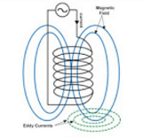
Pic 1
Eddy Current Testing uses the fact that when a an alternating current coil induces an electromagnetic field into a conductive test piece, a small current is created around the magnetic flux field, much like a magnetic field is generated around an electric current. The flow pattern of this secondary current, called an "eddy" current, will be affected when it encounters a discontinuity in the test piece, and the change in the eddy current density can be detected and used to characterize the discontinuity causing that change. A simplified schematic of eddy currents generated by an alternating current coil ("probe") is shown in Pic 1. By varying the type of coil, this test method can be applied to flat surfaces or tubular products. This technique works best on smooth surfaces and has limited penetration, usually less than ¼".
Pic 2
Encircling coils (Pic 2) are used to test tubular and bar-shaped products. The tube or bar can be fed through the coil at a relatively high speed, allowing the full cross-section of the test object to be interrogated. However, due to the direction of the flux lines, circumferentially oriented discontinuities may not be detected with this application.
2. Alternating Current Field Measurement
Alternating Current Field Measurement (ACFM) uses a specialized probe that introduces an alternating current into the surface of the test piece, creating a magnetic field. In parts with no discontinuities this field will be uniform, but if there is a discontinuity open to the surface, the magnetic field will flow around and under the discontinuity, causing a disruption of the field that can be detected by sensors within the probe. The resulting feedback can then be fed to software that can determine the length and depth of the discontinuity. ACFM provides better results on rough surfaces than Eddy Current and can be used through many surface coatings.
3. Remote Field Testing (RFT)
Remote Field Testing (RFT) is most commonly used to inspect ferromagnetic tubing due to the presence of a strong skin effect found in such tubes. Compared to standard eddy current techniques, remote field testing provides better results throughout the thickness of the tube, having approximately equal sensitivity at both the ID and OD surfaces of the tube. For non-ferromagnetic tubes, eddy current tends to provide more sensitivity.
