
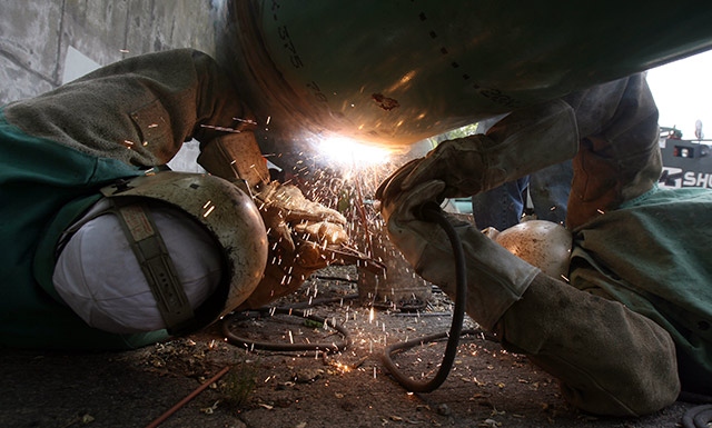


Visual testing is the most commonly used test method in industry. Because most test methods require that the operator look at the surface of the part being inspected, visual inspection is inherent in most of the other test methods. As the name implies, VT involves the visual observation of the surface of a test object to evaluate the presence of surface discontinuities. VT inspections may be by Direct Viewing, using line-of sight vision, or may be enhanced with the use of optical instruments such as magnifying glasses, mirrors, boroscopes, charge-coupled devices (CCDs) and computer-assisted viewing systems (Remote Viewing). Corrosion, misalignment of parts, physical damage and cracks are just some of the discontinuities that may be detected by visual examinations.

Ultrasonic Testing (UT)

Picture 1
Ultrasonic Testing uses the same principle as is used in
naval SONAR and fish finders. Ultra-high frequency sound is introduced into the
part being inspected and if the sound hits a material with a different acoustic
impedance (density and acoustic velocity), some of the sound will reflect back
to the sending unit and can be presented on a visual display. By knowing the
speed of the sound through the part (the acoustic velocity) and the time
required for the sound to return to the sending unit, the distance to the
reflector (the indication with the different acoustic impedance) can be
determined. The most common sound frequencies used in UT are between 1.0 and
10.0 MHz, which are too high to be heard and do not travel through air. The
lower frequencies have greater penetrating power but less sensitivity (the
ability to "see" small indications), while the higher frequencies
don't penetrate as deeply but can detect smaller indications.
The two most commonly used types of sound waves used in
industrial inspections are the compression (longitudinal) wave and the shear
(transverse) wave, as shown in picture 1. Compression waves cause the atoms in
a part to vibrate back and forth parallel to the sound direction and shear
waves cause the atoms to vibrate perpendicularly (from side to side) to the
direction of the sound. Shear waves travel at approximately half the speed of
longitudinal waves.
Sound is introduced into the part using an ultrasonic
transducer ("probe") that converts electrical impulses from the UT
machine into sound waves, then converts returning sound back into electric
impulses that can be displayed as a visual representation on a digital or LCD
screen (on older machines, a CRT screen). If the machine is properly
calibrated, the operator can determine the distance from the transducer to the
reflector, and in many cases, an experienced operator can determine the type of
discontinuity (like slag, porosity or cracks in a weld) that caused the
reflector. Because ultrasound will not travel through air (the atoms in air
molecules are too far apart to transmit ultrasound), a liquid or gel called
"couplant" is used between the face of the transducer and the surface
of the part to allow the sound to be transmitted into the part.
UT Techniques
Straight Beam
Picture 2
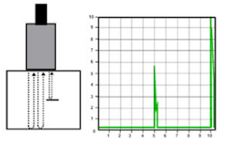
Straight beam inspection uses longitudinal waves to
interrogate the test piece as shown at the right. If the sound hits an internal
reflector, the sound from that reflector will reflect to the transducer faster
than the sound coming back from the back-wall of the part due to the shorter
distance from the transducer. This results in a screen display like that shown
at the right in Picture 2. Digital thickness testers use the same process, but
the output is shown as a digital numeric readout rather than a screen
presentation.
Angle Beam

Picture 3
Angle beam inspection uses the same type of transducer but
it is mounted on an angled wedge (also called a "probe") that is
designed to transmit the sound beam into the part at a known angle. The most
commonly used inspection angles are 45o, 60o and 70o, with the angle being
calculated up from a line drawn through the thickness of the part (not the part
surface). A 60o probe is shown in Picture 3. If the frequency and wedge angle
is not specified by the governing code or specification, it is up to the
operator to select a combination that will adequately inspect the part being
tested.
In angle beam inspections, the transducer and wedge
combination (also referred to as a "probe") is moved back and forth
towards the weld so that the sound beam passes through the full volume of the
weld. As with straight beam inspections, reflectors aligned more or less
perpendicular to the sound beam will send sound back to the transducer and are
displayed on the screen.
Immersion Testing

Picture 4
Immersion Testing is a technique where the part is immersed
in a tank of water with the water being used as the coupling medium to allow
the sound beam to travel between the transducer and the part. The UT machine is
mounted on a movable platform (a "bridge") on the side of the tank so
it can travel down the length of the tank. The transducer is swivel-mounted on
at the bottom of a waterproof tube that can be raised, lowered and moved across
the tank. The bridge and tube movement permits the transducer to be moved on
the X-, Y- and Z-axes. All directions of travel are gear driven so the
transducer can be moved in accurate increments in all directions, and the
swivel allows the transducer to be oriented so the sound beam enters the part
at the required angle. Round test parts are often mounted on powered rollers so
that the part can be rotated as the transducer travels down its length,
allowing the full circumference to be tested. Multiple transducers can be used
at the same time so that multiple scans can be performed.
Through Transmission
Through transmission inspections are performed using two
transducers, one on each side of the part as shown in Picture 4. The
transmitting transducer sends sound through the part and the receiving
transducer receives the sound. Reflectors in the part will cause a reduction in
the amount of sound reaching the receiver so that the screen presentation will
show a signal with a lower amplitude (screen height).
Phased Array
Phased array inspections are done using a probe with multiple
elements that can be individually activated. By varying the time when each
element is activated, the resulting sound beam can be "steered", and
the resulting data can be combined to form a visual image representing a slice
through the part being inspected.
Time of Flight Diffraction
Time of Flight Diffraction (TOFD) uses two transducers
located on opposite sides of a weld with the transducers set at a specified
distance from each other. One transducer transmits sound waves and the other
transducer acting as a receiver. Unlike other angle beam inspections, the
transducers are not manipulated back and forth towards the weld, but travel
along the length of the weld with the transducers remaining at the same
distance from the weld. Two sound waves are generated, one travelling along the
part surface between the transducers, and the other travelling down through the
weld at an angle then back up to the receiver. When a crack is encountered,
some of the sound is diffracted from the tips of the crack, generating a low
strength sound wave that can be picked up by the receiving unit. By amplifying
and running these signals through a computer, defect size and location can be
determined with much greater accuracy than by conventional UT methods.
Radiographic Testing (RT)
RADIOGRAPHY TEST
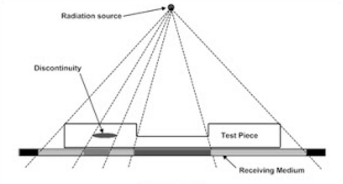
Industrial radiography involves exposing a test object to
penetrating radiation so that the radiation passes through the object being
inspected and a recording medium placed against the opposite side of that
object. For thinner or less dense materials such as aluminum, electrically
generated x-radiation (X-rays) are commonly used, and for thicker or denser
materials, gamma radiation is generally used.
Gamma radiation is given off by decaying radioactive
materials, with the two most commonly used sources of gamma radiation being
Iridium-192 (Ir-192) and Cobalt-60 (Co-60). IR-192 is generally used for steel
up to 2-1/2 - 3 inches, depending on the Curie strength of the source, and
Co-60 is usually used for thicker materials due to its greater penetrating
ability.
The recording media can be industrial x-ray film or one of
several types of digital radiation detectors. With both, the radiation passing
through the test object exposes the media, causing an end effect of having
darker areas where more radiation has passed through the part and lighter areas
where less radiation has penetrated. If there is a void or defect in the part,
more radiation passes through, causing a darker image on the film or detector,
as shown in Figure 8.
RT Techniques
Film Radiography

Film radiography uses a film made up of a thin transparent
plastic coated with a fine layer of silver bromide on one or both sides of the
plastic. When exposed to radiation these crystals undergo a reaction that
allows them, when developed, to convert to black metallic silver. That silver
is then "fixed" to the plastic during the developing process, and
when dried, becomes a finished radiographic film.
To be a usable film, the area of interest (weld area, etc.)
on the film must be within a certain density (darkness) range and must show
enough contrast and sensitivity so that discontinuities of interest can be
seen. These items are a function of the strength of the radiation, the distance
of the source from the film and the thickness of the part being inspected. If
any of these parameters are not met, another exposure ("shot") must
be made for that area of the part.
Computed Radiography

Computed radiography (CR) is a transitional technology
between film and direct digital radiography. This technique uses a reusable,
flexible, photo-stimulated phosphor (PSP) plate which is loaded into a cassette
and is exposed in a manner similar to traditional film radiography. The
cassette is then placed in a laser reader where it is scanned and translated
into a digital image, which take from one to five minutes. The image can then
be uploaded to a computer or other electronic media for interpretation and
storage.
Computed Tomography
Computed tomography (CT) uses a computer to reconstruct an
image of a cross sectional plane of an object as opposed to a conventional
radiograph, as shown in Figure 9. The CT image is developed from multiple views
taken at different viewing angles that are reconstructed using a computer. With
traditional radiography, the position of internal discontinuities cannot be
accurately determined without making exposures from several angles to locate
the item by triangulation. With computed tomography, the computer triangulates
using every point in the plane as viewed from many different directions.
Digital Radiography
Digital radiography (DR) digitizes the radiation that passes
through an object directly into an image that can be displayed on a computer
monitor. The three principle technologies used in direct digital imaging are
amorphous silicon, charge coupled devices (CCDs), and complementary metal oxide
semiconductors (CMOSs). These images are available for viewing and analysis in
seconds compared to the time needed to scan in computed radiography images. The
increased processing speed is a result of the unique construction of the
pixels; an arrangement that also allows a superior resolution than is found in
computed radiography and most film applications.
Subscribe to:
Posts (Atom)