Leak Testing, 

Leak Testingas the name implies, is used to detect through leaks using one of the four major LT techniques: Bubble, Pressure Change, Halogen Diode and Mass Spectrometer Testing. These techniques are described below.


LT Techniques

Bubble Leak Testing

Pic 1 : Leak Test

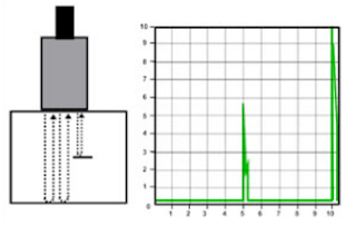
Bubble Leak Testing, as the name implies, relies on the visual detection of a gas (usually air) leaking from a pressurized system. Small parts can be pressurized and immersed in a tank of liquid and larger vessels can be pressurized and inspected by spraying a soap solution that creates fine bubbles to the area being tested. For flat surfaces, the soap solution can be applied to the surface and a vacuum box Pic 1 can be used to create a negative pressure from the inspection side. If there are through leaks, bubbles will form, showing the location of the leak.

Pressure Change Testing

Pressure Change Testing can be performed on closed systems only. Detection of a leak is done by either pressurizing the system or pulling a vacuum then monitoring the pressure. Loss of pressure or vacuum over a set period of time indicates that there is a leak in the system. Changes in temperature within the system can cause changes in pressure, so readings may have to be adjusted accordingly.

Halogen Diode Testing

Halogen Diode Testing is done by pressurizing a system with a mixture of air and a halogen-based tracer gas. After a set period of time, a halogen diode detection unit, or "sniffer", is used to locate leaks.
Mass Spectrometer Testing

Mass Spectrometer Testing can be done by pressurizing the test part with helium or a helium/air mixture within a test chamber then surveying the surfaces using a sniffer, which sends an air sample back to the spectrometer. Another technique creates a vacuum within the test chamber so that the gas within the pressurized system is drawn into the chamber through any leaks. The mass spectrometer is then used to sample the vacuum chamber and any helium present will be ionized, making very small amounts of helium readily detectable.
 

Visual Testing (VT)

Visual testing is the most commonly used test method in industry. Because most test methods require that the operator look at the surface of the part being inspected, visual inspection is inherent in most of the other test methods. As the name implies, VT involves the visual observation of the surface of a test object to evaluate the presence of surface discontinuities. VT inspections may be by Direct Viewing, using line-of sight vision, or may be enhanced with the use of optical instruments such as magnifying glasses, mirrors, boroscopes, charge-coupled devices (CCDs) and computer-assisted viewing systems (Remote Viewing). Corrosion, misalignment of parts, physical damage and cracks are just some of the discontinuities that may be detected by visual examinations.
 

Ultrasonic Testing (UT)

 Ultrasonic Testing

Picture 1

Ultrasonic Testing uses the same principle as is used in naval SONAR and fish finders. Ultra-high frequency sound is introduced into the part being inspected and if the sound hits a material with a different acoustic impedance (density and acoustic velocity), some of the sound will reflect back to the sending unit and can be presented on a visual display. By knowing the speed of the sound through the part (the acoustic velocity) and the time required for the sound to return to the sending unit, the distance to the reflector (the indication with the different acoustic impedance) can be determined. The most common sound frequencies used in UT are between 1.0 and 10.0 MHz, which are too high to be heard and do not travel through air. The lower frequencies have greater penetrating power but less sensitivity (the ability to "see" small indications), while the higher frequencies don't penetrate as deeply but can detect smaller indications.

The two most commonly used types of sound waves used in industrial inspections are the compression (longitudinal) wave and the shear (transverse) wave, as shown in picture 1. Compression waves cause the atoms in a part to vibrate back and forth parallel to the sound direction and shear waves cause the atoms to vibrate perpendicularly (from side to side) to the direction of the sound. Shear waves travel at approximately half the speed of longitudinal waves.

Sound is introduced into the part using an ultrasonic transducer ("probe") that converts electrical impulses from the UT machine into sound waves, then converts returning sound back into electric impulses that can be displayed as a visual representation on a digital or LCD screen (on older machines, a CRT screen). If the machine is properly calibrated, the operator can determine the distance from the transducer to the reflector, and in many cases, an experienced operator can determine the type of discontinuity (like slag, porosity or cracks in a weld) that caused the reflector. Because ultrasound will not travel through air (the atoms in air molecules are too far apart to transmit ultrasound), a liquid or gel called "couplant" is used between the face of the transducer and the surface of the part to allow the sound to be transmitted into the part.


UT Techniques


Straight Beam
Picture 2

Straight beam inspection uses longitudinal waves to interrogate the test piece as shown at the right. If the sound hits an internal reflector, the sound from that reflector will reflect to the transducer faster than the sound coming back from the back-wall of the part due to the shorter distance from the transducer. This results in a screen display like that shown at the right in Picture 2. Digital thickness testers use the same process, but the output is shown as a digital numeric readout rather than a screen presentation.

Angle Beam


Picture 3


Angle beam inspection uses the same type of transducer but it is mounted on an angled wedge (also called a "probe") that is designed to transmit the sound beam into the part at a known angle. The most commonly used inspection angles are 45o, 60o and 70o, with the angle being calculated up from a line drawn through the thickness of the part (not the part surface). A 60o probe is shown in Picture 3. If the frequency and wedge angle is not specified by the governing code or specification, it is up to the operator to select a combination that will adequately inspect the part being tested.

In angle beam inspections, the transducer and wedge combination (also referred to as a "probe") is moved back and forth towards the weld so that the sound beam passes through the full volume of the weld. As with straight beam inspections, reflectors aligned more or less perpendicular to the sound beam will send sound back to the transducer and are displayed on the screen.

Immersion Testing


Picture 4


Immersion Testing is a technique where the part is immersed in a tank of water with the water being used as the coupling medium to allow the sound beam to travel between the transducer and the part. The UT machine is mounted on a movable platform (a "bridge") on the side of the tank so it can travel down the length of the tank. The transducer is swivel-mounted on at the bottom of a waterproof tube that can be raised, lowered and moved across the tank. The bridge and tube movement permits the transducer to be moved on the X-, Y- and Z-axes. All directions of travel are gear driven so the transducer can be moved in accurate increments in all directions, and the swivel allows the transducer to be oriented so the sound beam enters the part at the required angle. Round test parts are often mounted on powered rollers so that the part can be rotated as the transducer travels down its length, allowing the full circumference to be tested. Multiple transducers can be used at the same time so that multiple scans can be performed.
Through Transmission
Through transmission inspections are performed using two transducers, one on each side of the part as shown in Picture 4. The transmitting transducer sends sound through the part and the receiving transducer receives the sound. Reflectors in the part will cause a reduction in the amount of sound reaching the receiver so that the screen presentation will show a signal with a lower amplitude (screen height).

Phased Array

Phased array inspections are done using a probe with multiple elements that can be individually activated. By varying the time when each element is activated, the resulting sound beam can be "steered", and the resulting data can be combined to form a visual image representing a slice through the part being inspected.

Time of Flight Diffraction

Time of Flight Diffraction (TOFD) uses two transducers located on opposite sides of a weld with the transducers set at a specified distance from each other. One transducer transmits sound waves and the other transducer acting as a receiver. Unlike other angle beam inspections, the transducers are not manipulated back and forth towards the weld, but travel along the length of the weld with the transducers remaining at the same distance from the weld. Two sound waves are generated, one travelling along the part surface between the transducers, and the other travelling down through the weld at an angle then back up to the receiver. When a crack is encountered, some of the sound is diffracted from the tips of the crack, generating a low strength sound wave that can be picked up by the receiving unit. By amplifying and running these signals through a computer, defect size and location can be determined with much greater accuracy than by conventional UT methods.
 

Radiographic Testing (RT)

RADIOGRAPHY TEST

Industrial radiography involves exposing a test object to penetrating radiation so that the radiation passes through the object being inspected and a recording medium placed against the opposite side of that object. For thinner or less dense materials such as aluminum, electrically generated x-radiation (X-rays) are commonly used, and for thicker or denser materials, gamma radiation is generally used.

Gamma radiation is given off by decaying radioactive materials, with the two most commonly used sources of gamma radiation being Iridium-192 (Ir-192) and Cobalt-60 (Co-60). IR-192 is generally used for steel up to 2-1/2 - 3 inches, depending on the Curie strength of the source, and Co-60 is usually used for thicker materials due to its greater penetrating ability.

The recording media can be industrial x-ray film or one of several types of digital radiation detectors. With both, the radiation passing through the test object exposes the media, causing an end effect of having darker areas where more radiation has passed through the part and lighter areas where less radiation has penetrated. If there is a void or defect in the part, more radiation passes through, causing a darker image on the film or detector, as shown in Figure 8.

RT Techniques

Film Radiography


Film radiography uses a film made up of a thin transparent plastic coated with a fine layer of silver bromide on one or both sides of the plastic. When exposed to radiation these crystals undergo a reaction that allows them, when developed, to convert to black metallic silver. That silver is then "fixed" to the plastic during the developing process, and when dried, becomes a finished radiographic film.

To be a usable film, the area of interest (weld area, etc.) on the film must be within a certain density (darkness) range and must show enough contrast and sensitivity so that discontinuities of interest can be seen. These items are a function of the strength of the radiation, the distance of the source from the film and the thickness of the part being inspected. If any of these parameters are not met, another exposure ("shot") must be made for that area of the part.

Computed Radiography


Computed radiography (CR) is a transitional technology between film and direct digital radiography. This technique uses a reusable, flexible, photo-stimulated phosphor (PSP) plate which is loaded into a cassette and is exposed in a manner similar to traditional film radiography. The cassette is then placed in a laser reader where it is scanned and translated into a digital image, which take from one to five minutes. The image can then be uploaded to a computer or other electronic media for interpretation and storage.

Computed Tomography

Computed tomography (CT) uses a computer to reconstruct an image of a cross sectional plane of an object as opposed to a conventional radiograph, as shown in Figure 9. The CT image is developed from multiple views taken at different viewing angles that are reconstructed using a computer. With traditional radiography, the position of internal discontinuities cannot be accurately determined without making exposures from several angles to locate the item by triangulation. With computed tomography, the computer triangulates using every point in the plane as viewed from many different directions.


Digital Radiography

Digital radiography (DR) digitizes the radiation that passes through an object directly into an image that can be displayed on a computer monitor. The three principle technologies used in direct digital imaging are amorphous silicon, charge coupled devices (CCDs), and complementary metal oxide semiconductors (CMOSs). These images are available for viewing and analysis in seconds compared to the time needed to scan in computed radiography images. The increased processing speed is a result of the unique construction of the pixels; an arrangement that also allows a superior resolution than is found in computed radiography and most film applications.
 

Liquid Penetrant Testing (PT)

Liquid Penetrant Testing (PT)

Pic1 : Using Penetrant Test


The basic principle of liquid penetrant testing is that when a very low viscosity (highly fluid) liquid (the penetrant) is applied to the surface of a part, it will penetrate into fissures and voids open to the surface. Once the excess penetrant is removed, the penetrant trapped in those voids will flow back out, creating an indication. Penetrant testing can be performed on magnetic and non-magnetic materials, but does not work well on porous materials. Penetrants may be "visible", meaning they can be seen in ambient light, or fluorescent, requiring the use of a "black" light. The visible dye penetrant process is shown in Pic 1. When performing a PT inspection, it is imperative that the surface being tested is clean and free of any foreign materials or liquids that might block the penetrant from entering voids or fissures open to the surface of the part. After applying the penetrant, it is permitted to sit on the surface for a specified period of time (the "penetrant dwell time"), then the part is carefully cleaned to remove excess penetrant from the surface. When removing the penetrant, the operator must be careful not to remove any penetrant that has flowed into voids. A light coating of developer is then be applied to the surface and given time ("developer dwell time") to allow the penetrant from any voids or fissures to seep up into the developer, creating a visible indication. Following the prescribed developer dwell time, the part is inspected visually, with the aid of a black light for fluorescent penetrants. Most developers are fine-grained, white talcum-like powders that provide a color contrast to the penetrant being used.


Steps to use of penetrant

1.Clean the surface of the material

Pic 2 : Use Cleaner/ Removal

Cleaned the surface of test beforehand to dirt , paint , oil , or plump did not result in an indication that are not very relevant or false .A method of cleansing can use a cleaning fluid ( cleaner / remover ) , for cleansing redusi an alkali , or steam degreasing .The ultimate goal of this step is a surface that is cleanly in which each defect visible and formed to the surface , dry , and free from contamination.

2. Spray penetrant into the area to be inspection:


Pic 3 : Use Penetrant Liquid

Test penetrant were then applied to the surface of the material material tested. Penetrant should be given ' Dwelling Time ' to percolate into each possibilities defect that is usually 5 to 30 minutes. Dwelling Time especially depends on penetrant used, material tested and size deficiency sought. As expected, small hitch takes more time old in penetrasinya. Because the incompatible they need to be careful to not to apply a solvent based penetrant to the surface that will be examined with penetrant that has been washed.


3. Clean up the Penetrant

Pic 4 : Clean up the Penetrant

After used Penetrant Liquid, please to Clean up the Penetrant on workpiece, the clean up can use Cloat Former, the cleaner/remover can to spray at cloat former, and than clean up the work piece with cloat former.


4. Use Developer Liquid


Pic 5 : Use Developer Liquid

After penetrant have been in clean in the surface of a workpiece use cleaner , and next use developers on a workpiece , wait 5-1 minutes . If there is an indication defect welds , so defect welds will appear in a workpiece

Developers interesting penetrant from defect come out to the surface to form a visible indication , is commonly known as blood - out .Any area blood - out can indicating the location of the , orientation and a kind of the possibility of a flaw on a surface. Interpret the results and characterization flaws in an indication that discoveries could be require various training and / or experience size an indication is not actual size from defect.


5. Inspection

Pic 6 : Inspection


Inspector will use visible light in intensity adequate ( 100 feet -- wax or 1100 lux typical ) to dye penetrant look.Ultraviolet ( uv-a ) of radiation intensity adequate ( 1,000 mikro-watt per centimeters public square, along with low level light ambient ( less than 2 foot-candle ) for examination penetrant fluorescent.Inspection the surface test to do after 10 to 30 minutes development, based on the type of products.

6. Post Cleaning


Pic 7 : Post Cleaning


If already convinced with the indications defect welds that appears , then immediately do cleaning on a workpiece .To maintain a workpiece the lifetime .
 

Magnetic Particle Testing (MT)

Magnetic Particle Testing (MT)


Pic 1

Magnetic Particle Testing uses one or more magnetic fields to locate surface and near-surface discontinuities in ferromagnetic materials. The magnetic field can be applied with a permanent magnet or an electromagnet. When using an electromagnet, the field is present only when the current is being applied. When the magnetic field encounters a discontinuity transverse to the direction of the magnetic field, the flux lines produce a magnetic flux leakage field of their own as shown in Pic 1. Because magnetic flux lines don't travel well in air, when very fine colored ferromagnetic particles ("magnetic particles") are applied to the surface of the part the particles will be drawn into the discontinuity, reducing the air gap and producing a visible indication on the surface of the part. The magnetic particles may be a dry powder or suspended in a liquid solution, and they may be colored with a visible dye or a fluorescent dye that fluoresces under an ultraviolet ("black") light.


MT Techniques

1. Yokes
Pic 2


Most field inspections are performed using a Yoke
as shown at the right. As shown in pic 2, an electric coil is wrapped around a central core, and when the current is applied, a magnetic field is generated that extends from the core down through the articulated legs into the part. This is known as longitudinal magnetization because the magnetic flux lines run from one leg to the other.


Pic 3

When the legs are placed on a ferromagnetic part and the yoke is energized, a magnetic field is introduced into the part as shown in pic 3. Because the flux lines do run from one leg to the other, discontinuities oriented perpendicular to a line drawn between the legs can be found. To ensure no indications are missed, the yoke is used once in the position shown then used again with the yoke turned 90o so no indications are missed. Because all of the electric current is contained in the yoke and only the magnetic field penetrates the part, this type of application is known as indirect induction.


2. Prods.
Pic 4

Prod units use direct inductionwhere the current runs through the part and a circular magnetic field is generated around the legs as shown in Pic 4. Because the magnetic field between the prods is travelling perpendicular to a line drawn between the prods, indications oriented parallel to a line drawn between the prods can be found. As with the yoke, two inspections are done, the second with the prods oriented 90o to the first application.

3. Coils.

Pic 5

Electric coils are used to generate a longitudinal magnetic field. When energized, the current creates a magnetic field around the wires making up the coil so that the resulting flux lines are oriented through the coil as shown at the right. Because of the longitudinal field, indications in parts placed in a coil are oriented transverse to the longitudinal field.


4. Heads

Pic 6


Most horizontal wet bath machines ("bench units") have both a coil and a set of heads through which electric current can be passed, generating a magnetic field. Most use fluorescent magnetic particles in a liquid solution, hence the name "wet bath." A typical bench unit is shown at the right. When testing a part between the heads, the part is placed between the heads, the moveable head is moved up so that the part being tested is held tightly between the heads, the part is wetted down with the bath solution containing the magnetic particles and the current is applied while the particle are flowing over the part. Since the current flow is from head to head and the magnetic field is oriented 90o to the current, indications oriented parallel to a line between the heads will be visible. This type of inspection is commonly called a "head shot."


5. Central Conductor

Pic 7

When testing hollow parts such as pipes, tubes and fittings, a conductive circular bar can be placed between the heads with the part suspended on the bar (the "central conductor") as shown in Pic 7. The part is then wetted down with the bath solution and the current is applied, travelling through the central conductor rather than through the part. The ID and OD of the part can then be inspected. As with a head shot, the magnetic field is perpendicular to the current flow, wrapping around the test piece, so indications running axially down the length of the part can be found using this technique.


NDT Technologies


Introduction to Nondestructive Testing


For visitors who are not already familiar with NDT, the general information below is intended to provide a basic description of NDT and the most common test methods and techniques used when performing NDT. As such it is not highly detailed or all encompassing, and for more comprehensive information readers should refer to ASNT publications such as the ASNT NDT Handbooks or the ASNT Personnel Training Publications (PTP) Classroom Training Series, all of which are available from ASNT’s bookstore. Also, standards covering these test methods are listed on the "Codes and Standards Bodies" page under the NDT Resources Center tab. To maintain consistency, the techniques described for each test method are those listed in the 2011 edition of ASNT’s Recommended Practice No. SNT-TC-1A.


What Is Nondestructive Testing?

Nondestructive testing (NDT) is the process of inspecting, testing, or evaluating materials, components or assemblies for discontinuities, or differences in characteristics without destroying the serviceability of the part or system. In other words, when the inspection or test is completed the part can still be used.


In contrast to NDT, other tests are destructive in nature and are therefore done on a limited number of samples ("lot sampling"), rather than on the materials, components or assemblies actually being put into service.


These destructive tests are often used to determine the physical properties of materials such as impact resistance, ductility, yield and ultimate tensile strength, fracture toughness and fatigue strength, but discontinuities and differences in material characteristics are more effectively found by NDT.


Today modern nondestructive tests are used in manufacturing, fabrication and in-service inspections to ensure product integrity and reliability, to control manufacturing processes, lower production costs and to maintain a uniform quality level. During construction, NDT is used to ensure the quality of materials and joining processes during the fabrication and erection phases, and in-service NDT inspections are used to ensure that the products in use continue to have the integrity necessary to ensure their usefulness and the safety of the public.


It should be noted that while the medical field uses many of the same processes, the term "nondestructive testing" is generally not used to describe medical applications.
NDT Test Methods


Test method names often refer to the type of penetrating medium or the equipment used to perform that test. Current NDT methods are: Acoustic Emission Testing (AE), Electromagnetic Testing (ET), Guided Wave Testing (GW), Ground Penetrating Radar (GPR), Laser Testing Methods (LM), Leak Testing (LT), Magnetic Flux Leakage (MFL), Microwave Testing, Liquid Penetrant Testing (PT), Magnetic Particle Testing (MT), Neutron Radiographic Testing (NR), Radiographic Testing (RT), Thermal/Infrared Testing (IR), Ultrasonic Testing (UT), Vibration Analysis (VA) and Visual Testing (VT).


The six most frequently used test methods are MT, PT, RT, UT, ET and VT. Each of these test methods will be described here, followed by the other, less often used test methods.
 

How to Become Welding Inspector


Should I Become a Welding Inspector?

Welding inspectors examine the connections and bonds between metals. Inspectors use visual tools and electrical instruments to check and ensure the quality and safety of connections.

In addition to working in the field completing their examinations of welding projects, inspectors spend time in an office setting compiling their reports. The majority of inspectors work on a full-time basis, primarily during business workdays. Some risk may be associated with this profession; welding inspectors utilize protective gear during their evaluations to keep themselves from harm on welding sites.


Career Requirements


Degree Level : High school diploma; postsecondary education can help students advance to a welding inspector position

Degree Field : Engineering, engineering technology

Experience : Varies; instructor certification requires 3-12 years experience, depending on education

Certification : Certification may be required or preferred by employers

Key Skills : Ability to perform physical work and climbing as part of the job, communication skills, familiarity with blueprint reading, familiarity with Microsoft Word and Excel

Salary (2015) : $68,507 yearly (median)


Sources: American Welding Society, Job listings accessed during December 2012, PayScale.com (July 2015)

Step 1: Earn a Postsecondary Education


Formal training through a community college or vocational school isn't required, but some employers seek welding inspectors with postsecondary education. Technical programs in welding typically last 1-2 years and result in a welding diploma or certificate. Topics generally include blueprint reading, metallurgy, fabrication and arc welding. Students might also consider 2-year associate's degree programs in welding technology. These programs often include general education coursework as well as welding-specific classes in arc, gas tungsten arc and pipe welding.

Success Tip:

Bolster related skills. Skills in creating objects and designing diagrams can be developed in courses like mathematics, wood or metal shop and drafting. Welding inspectors must use mathematics in calculations to determine the strength of the weld as well as drafting skills to examine and evaluate other welders' designs.

Step 2: Gain Work Experience

Welders work in a variety of industries, including construction, aerospace and machinery manufacturing. Before moving into the role of inspector, welders might perform entry-level work, such as cleaning and degreasing parts, checking angles and dimensions for accuracy, inspecting equipment and mixing and applying protective coatings.


As new hires gain experience, they might advance to reading blueprints and using their knowledge and skills in metallurgy and welding to join, bind and fuse two or more metals together. Skilled welders might move on to even more complex tasks, such as welding difficult angles or materials, like titanium or steel. Advanced welders can also develop templates and models, estimate parts and labor costs and examine work for defects. Promotion to welding inspector could include duties like writing inspection reports, ensuring that equipment complies with engineering, welding and testing standards and training other welding staff.

Success Tip: 

Participate in an apprenticeship or internship. Completion of an internship is one way to gain experience in the welding field. Some unions will assist aspiring welders in securing internships.


Step 3: Pass Welding Inspector Certification Exam

Welders who have attained a postsecondary certificate, diploma or degree and completed 3-4 years of documented work experience may apply to become Certified Welding Inspectors (CWIs) from the American Welding Society (AWS). The certification exam covers three areas, including welding fundamentals, practical applications and welding code application. Certifications generally last three years; however, CWIs can take additional exams or courses in order to prolong recertification for up to nine years.

Success Tip:
Consider attaining endorsements. CWIs also can earn supplemental inspection credentials. While not required, these endorsements might allow CWIs to execute inspections that might have been excluded due to customer or jurisdictional requirements, such as inspections of bridges and railroads. Upon passage of a qualifying codebook exam, inspectors are given a separate endorsement card and certificate of completion.